ESP8266 WiFi Module
Overview of the ESP8266 WiFi Module

The ESP8266 requires 3.3V power--do not power it with 5 volts
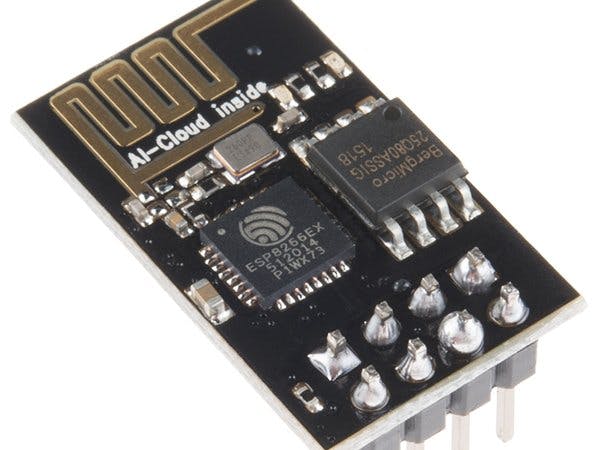
The ESP8266 is a really useful, cheap WiFi module for controlling devices over the Internet. It can work with a microcontroller like the Arduino or it can be programmed to work on its own.
The Internet of Things (IoT) has just been made a whole lot cheaper and easier!
The ESP8266 comes with factory-installed firmware allowing you to control it with standard “AT commands”. You can also easily create and upload your own code and this makes it hugely powerful and flexible.
We’ll be replacing the firmware with our own code. In another instructable: The Simple Guide to Flashing Your ESP8266 Firmware I show you how to revert it back to an updated factory version. If you'll only be programming the ESP8266 with your own code - as we will be doing in this demo - then you don't need factory firmware. Your code is the firmware.
We'll be using the Arduino IDE as a programming tool but we don't need an Arduino itself. The ESP8266 has all the functionality we need.
Note: that after uploading your own code, your ESP8266 won't respond to AT commands anymore. Your code has replaced the firmware. Using your code and the ESP8266 library in the Arduino IDE you'll have access to a richer set of commands. See the documentation here: https://www.arduino.cc/en/Reference/WiFi
You can restore the firmware on the ESP8266 to go back to AT commands if you wish. See my other instructable: The Simple Guide to Flashing Your ESP8266 Firmware.


NodeMCU is an open-source Lua based firmware and development board specially targeted for IoT based Applications. It includes firmware that runs on the ESP8266 Wi-Fi SoC from Espressif Systems, and hardware which is based on the ESP-12 module.
NodeMCU Development Board Pinout Configuration
Pin Category | Name | Description |
Power | Micro-USB, 3.3V, GND, Vin | Micro-USB: NodeMCU can be powered through the USB port
3.3V: Regulated 3.3V can be supplied to this pin to power the board
GND: Ground pins
Vin: External Power Supply |
Control Pins | EN, RST | The pin and the button resets the microcontroller |
Analog Pin | A0 | Used to measure analog voltage in the range of 0-3.3V |
GPIO Pins | GPIO1 to GPIO16 | NodeMCU has 16 general purpose input-output pins on its board |
SPI Pins | SD1, CMD, SD0, CLK | NodeMCU has four pins available for SPI communication. |
UART Pins | TXD0, RXD0, TXD2, RXD2 | NodeMCU has two UART interfaces, UART0 (RXD0 & TXD0) and UART1 (RXD1 & TXD1). UART1 is used to upload the firmware/program. |
I2C Pins |
| NodeMCU has I2C functionality support but due to the internal functionality of these pins, you have to find which pin is I2C. |
NodeMCU ESP8266 Specifications & Features
- Microcontroller: Tensilica 32-bit RISC CPU Xtensa LX106
- Operating Voltage: 3.3V
- Input Voltage: 7-12V
- Digital I/O Pins (DIO): 16
- Analog Input Pins (ADC): 1
- UARTs: 1
- SPIs: 1
- I2Cs: 1
- Flash Memory: 4 MB
- SRAM: 64 KB
- Clock Speed: 80 MHz
- USB-TTL based on CP2102 is included onboard, Enabling Plug n Play
- PCB Antenna
- Small Sized module to fit smartly inside your IoT projects

Pins are arranged in two rows, having 4 on each row. Some models have pin description on the PCB, which make it simple. On the top row you can find following pins from the left to the right:
- GND (Ground from power supply)
- GPIO2 (Digital I/O programmable)
- GPIO0 (Digital I/O programmable, also used for BOOT modes)
- RX – UART Receiving channel
On the bottom (second row) you can find:
- TX – UART Transmitting channel
- CH_PD (enable/power down, must be pulled to 3.3v directly or via resistor)
- REST – reset, must be pulled to 3.3v)
- VCC -3.3v power supply

Comments